Relays and Motor Control Symbols: Relay vs. Contactor Explained
A contactor is a relay built to switch much higher current — the distinction that trips up a lot of motor control wiring diagrams. Relay vs. contactor, how overload relays protect motors, and NEMA vs. IEC symbol differences.
July 22, 2026 ·
Updated July 23, 2026 ·
6 min read ·
SCMEP Training Team ·
181 views
Share
A contactor is really just a heavy-duty relay — the distinction isn’t
category, it’s capacity. Once you know what each is actually rated to
switch, motor control wiring stops looking like a tangle of coils and
starts reading as a straightforward story: something small controlling
something big.
Relay vs. contactor
Relays and contactors compared
Relay
Contactor
Typical rating
Fractions of an amp up to roughly 10-15A
15A up to several hundred amps
Contacts
Mixed normally-open and normally-closed, often with a common pole
Almost always normally-open, no common/neutral pole
Typical load
Pilot lights, small solenoids, PLC I/O interposing
Motors, heaters, three-phase loads
Arc suppression
Minimal
Built-in arc chutes or blowouts for breaking large loads
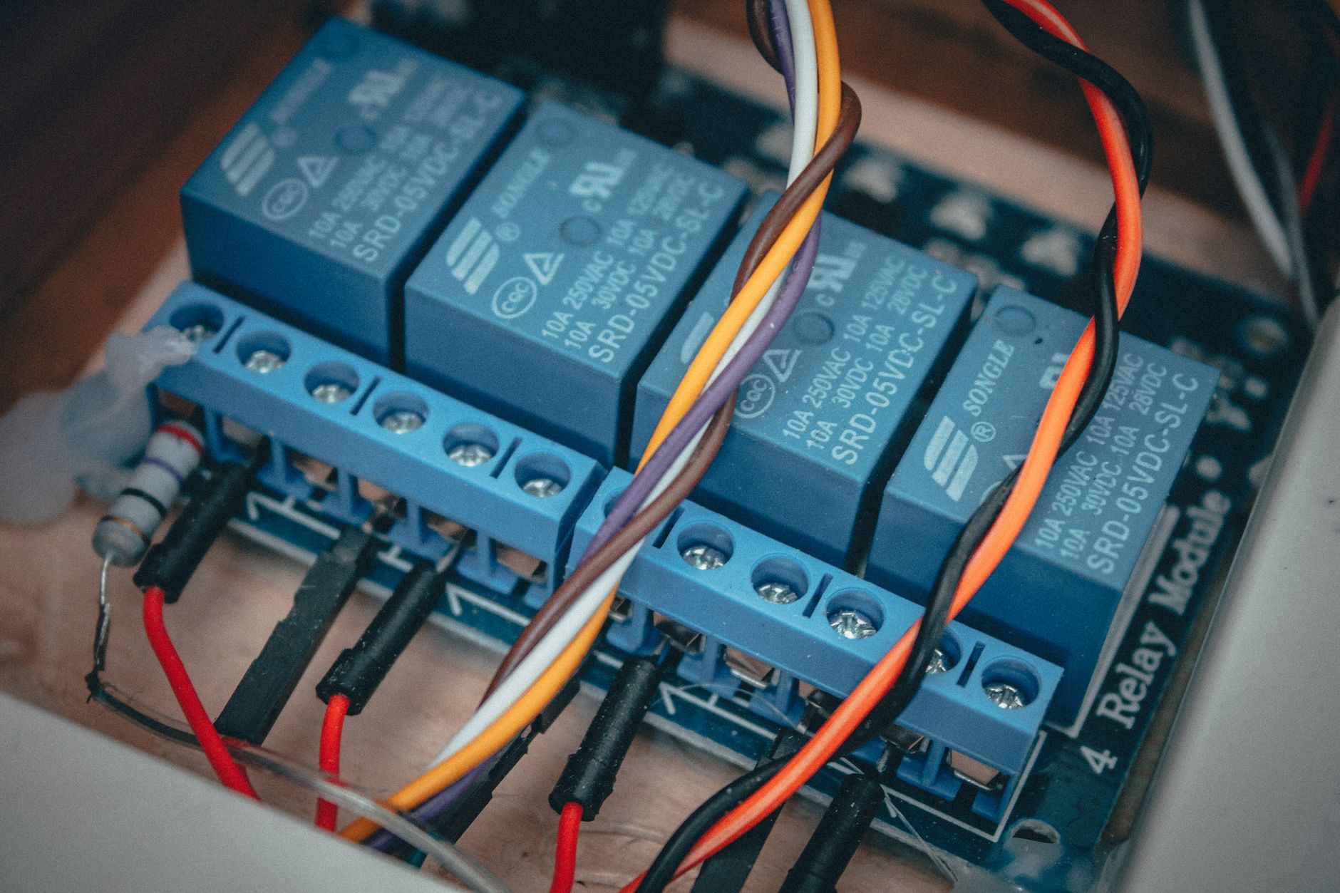
The reason a contactor exists as its own category rather than just a
“big relay” is that switching a motor’s current safely requires handling
the arc that forms as the contacts separate under load — a relay’s
smaller contacts and lack of arc suppression aren’t built for that job,
and using one to switch motor-sized current will burn the contacts fast.
How an overload relay actually protects a motor
A magnetic or thermal overload relay sits between the contactor and
the motor, sensing the current flowing to the motor and tripping if it
stays too high for too long — protecting against a stalled or overloaded
motor cooking its windings, not against a sudden short circuit (that’s a
fuse or breaker’s job). Thermal overloads use a bimetallic strip or
eutectic alloy that heats up with sustained overcurrent and mechanically
trips an auxiliary contact; electronic overloads use current
transformers instead and can add protection against phase loss or
imbalance that a purely thermal device can’t detect.
Reading the schematic symbols
NEMA (the US convention) and IEC (the international convention) use
visibly different symbol sets for the same devices — a NEMA-style
drawing represents a normally-open contact and a coil differently than
an IEC-style one does. Reading a schematic drawn to the wrong convention
as if it were the other produces genuine confusion, not just a stylistic
mismatch. Before troubleshooting off any print, check which convention
it’s drawn to, especially on imported equipment or drawings from an
overseas OEM.
Both conventions represent the same underlying logic — a contact
symbol showing an open or closed gap, a coil symbol showing the device
being energized — the actual visual shapes and line styles are just
different enough between the two systems to cause real misreads if you
assume the wrong one.
A basic motor starter, wired out
The power side runs L1/L2/L3 through the contactor, through the
overload relay’s heater elements, and out to the motor’s T1/T2/T3
terminals. The control side is a separate, lower-current circuit: power
through a normally-closed Stop button, into a normally-open Start button,
into the contactor’s coil — with a normally-open auxiliary contact wired
in parallel with Start, sealing the circuit in once the coil energizes so
the motor stays running after Start is released. The overload relay’s
normally-closed contact sits in series in that same coil circuit, so a
trip drops the motor regardless of what the seal-in contact is doing.
This is the same seal-in logic covered in our Siemens PLC ladder logic guide —
a PLC can replace the physical Start/Stop/seal-in wiring with a rung of
logic, but the contactor and overload relay downstream are still doing
the same physical job of actually switching and protecting the motor.
That’s a useful way to think about the relationship between the two
posts: the PLC decides when the motor should run; the contactor and
overload relay are the physical muscle and the physical safety net that
actually make it happen and keep it from destroying itself. Neither one
replaces the other — a PLC output still has to switch something rated
for the actual motor current, and that something is a contactor.
Troubleshooting starts with the coil, not the contacts
When a motor won’t start, checking whether the contactor’s coil is
actually receiving voltage is a faster first step than assuming the
contactor itself has failed. A coil with no voltage points back to the
control circuit — a tripped overload, an open Stop button, a bad seal-in
contact — while a coil with voltage that still isn’t pulling the
contacts in points to the contactor itself. That one check splits the
troubleshooting path in half before any contacts get pulled apart.
Relay logic and motor control symbols describe how a motor circuit is wired; a separate device actually controls how fast that motor runs. See our related guide on Variable Frequency Drives for how VFDs control motor speed and cut energy use.
Frequently asked questions
Is a contactor a type of relay?
Yes — a contactor is essentially a heavy-duty relay built to switch much higher current, almost always with normally-open contacts and built-in arc suppression for breaking motor-sized loads safely.
What’s the difference between a motor starter and a contactor?
A contactor is the switching device itself. A motor starter is the contactor combined with an overload relay for motor protection — the contactor alone doesn’t protect the motor from sustained overcurrent.
Why does my motor overload keep tripping?
An overload relay trips when it senses sustained overcurrent, which usually means the motor is mechanically overloaded, stalling, running on unbalanced phases, or the overload’s trip setting doesn’t match the motor’s actual full-load current rating.
What size contactor do I need for a motor?
Contactor sizing is based on the motor’s full-load current rating and starting characteristics, typically matched against the contactor manufacturer’s NEMA or IEC rating tables rather than picked by rough estimate.
South Carolina Manufacturing Extension Partnership has delivered manufacturing training to South Carolina manufacturers since 1989. Articles are produced and reviewed by SCMEP's training team.