Pneumatic Systems and Components: A Practical Guide
Compressed air runs a lot of a manufacturing floor quietly in the background. What's actually in a pneumatic system, how to read the ISO 1219 schematic, pneumatic vs. hydraulic, and common failure points.
July 22, 2026 ·
Updated July 23, 2026 ·
6 min read ·
SCMEP Training Team ·
179 views
Share
Compressed air runs a lot of a manufacturing floor quietly in the
background — cylinders, grippers, and simple automation that never show
up in conversations about robots or PLCs, but stop the line just as fast
when something fails. Here’s what’s actually in a pneumatic system, how
to read the schematic, and when pneumatic loses out to hydraulic.
What’s actually in a pneumatic system
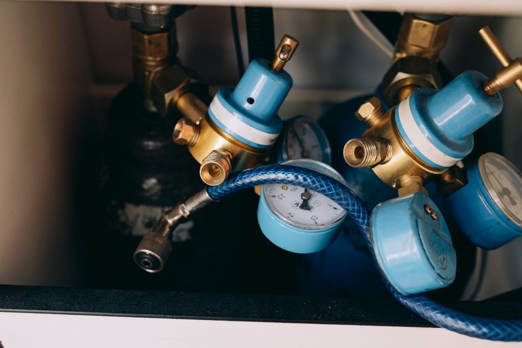
A pneumatic system starts with a compressor generating compressed air
(typically 80–125 psi shop air), stored in a receiver tank to smooth out
demand spikes. From there, air passes through an FRL unit — Filter,
Regulator, Lubricator — before reaching the actual work. The filter
removes particulates and moisture, the regulator sets and holds the
downstream pressure, and the lubricator adds a fine oil mist to reduce
wear on components downstream (worth noting: many modern components are
rated “non-lube,” so lubricators are increasingly left out — check your
component specs before assuming one’s needed).
From the FRL, air reaches a directional control valve (DCV) — commonly
a 3/2-way or 5/2-way solenoid valve — which routes air to an actuator:
a cylinder, rotary actuator, air motor, or gripper. Unlike a hydraulic
system, exhausted air simply vents to atmosphere rather than returning
through a closed loop, which is part of why pneumatic systems are
simpler to plumb but also noisier and less efficient at scale.
Reading a pneumatic schematic
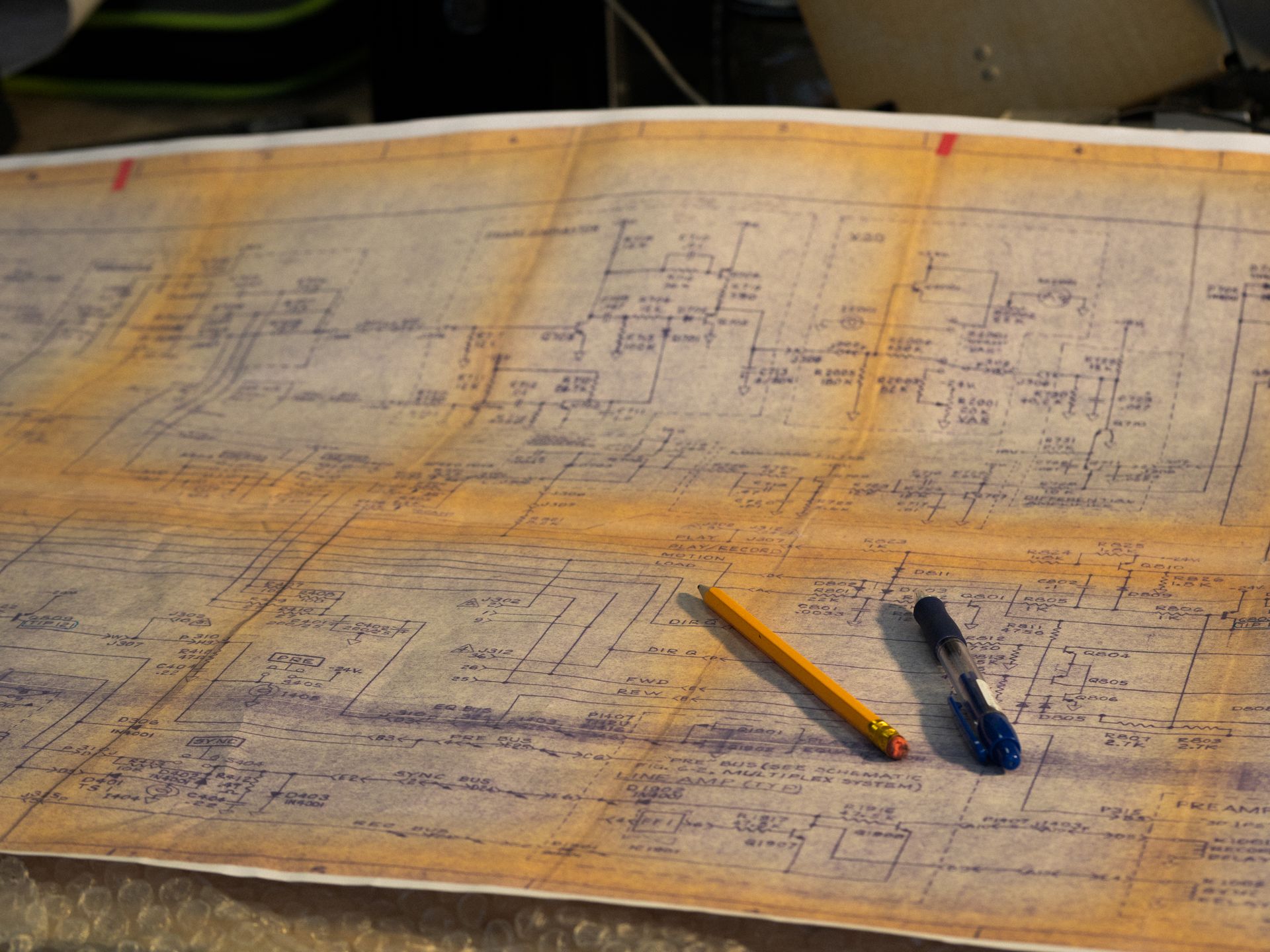
Pneumatic (and hydraulic) schematic symbols follow ISO 1219 — ISO
1219-1 for the graphical symbols themselves, ISO 1219-2 for how they’re
assembled into full circuit diagrams. Valves are drawn as boxes
containing flow-path squares, with arrows showing flow direction and a
separate symbol at the end of the valve box showing how it’s actuated —
solenoid, spring return, manual button, or pilot signal. Cylinders are
drawn as rectangles with a piston rod extending from one end; FRL
components, check valves, and flow-control valves each have their own
standard symbol. A muffler symbol on an exhaust port shows where air
vents to atmosphere.
Core pneumatic components and what they do
Component
Function
Compressor + receiver tank
Generates and stores compressed air, smoothing demand spikes
Air’s compressibility is the whole story here — it’s what makes
pneumatic systems cheap, fast-cycling, and leak-tolerant, and it’s
exactly what makes them a poor fit anywhere precise, held-position force
matters (a press that needs to hold exact clamping pressure, for
example). Hydraulic systems trade that simplicity for the precision and
raw force compressibility can’t deliver.
A useful rule of thumb when specifying a new system: if the
application is light, fast, and doesn’t need to hold a precise position
under load, pneumatic is usually the cheaper and simpler answer. If it
needs to move something heavy, hold a position precisely against
resistance, or apply consistent high force over time, hydraulic is
almost always the better fit even though it costs more upfront.
Common failure points worth knowing
Common pneumatic system problems and where to look
Symptom
Common cause
Cylinder cycles slowly or weakly
Low supply pressure, a clogged filter, or a leak somewhere in the line upstream
Valve won’t shift
Solenoid failure, low pilot pressure, or contamination in the valve spool
Excess moisture in the system
Undersized or failing filter/dryer, or a receiver tank that isn’t being drained
Premature seal wear
Missing lubrication on components that actually require it, or contaminated air
Most pneumatic troubleshooting starts at the FRL, not the actuator —
a cylinder that seems weak or inconsistent is very often a symptom of
something upstream (pressure, filtration, or a leak) rather than a
failing cylinder itself. Checking supply pressure and filter condition
before pulling apart an actuator saves a lot of unnecessary teardown.
Where this shows up in automation
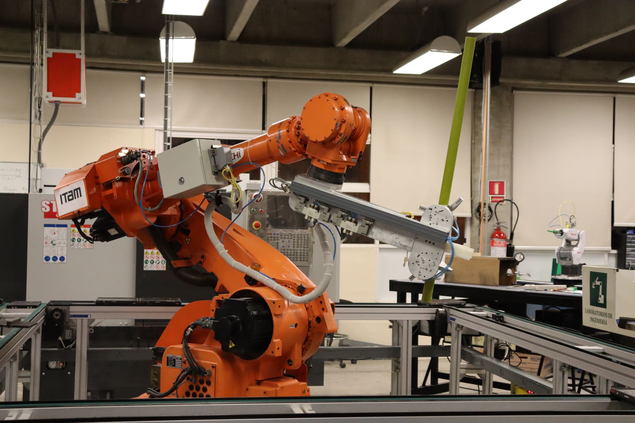
Pneumatic actuators and grippers are common on robotic end-effectors
and simple pick-and-place automation — often the same cobot cells covered
in our manufacturing robotics
training guide use a pneumatic gripper as the actual point of contact
with the part, even though the robot arm itself is electrically driven.
Maintaining that pneumatic side — FRL servicing, valve troubleshooting,
seal replacement — is a distinct, ongoing maintenance-tech skill from
programming the robot that moves it.
Pneumatic systems have a hydraulic counterpart worth knowing. See our
related guide on industrial
hydraulic systems for when high-force, precise applications call for
fluid power instead of compressed air.
Every pneumatic component in a system depends on compressed air being generated and distributed efficiently in the first place. Read our guide to compressed air system efficiency — finding the leaks that cost you.
Frequently asked questions
What is an FRL unit in a pneumatic system?
FRL stands for Filter, Regulator, Lubricator. The filter removes particulates and moisture from compressed air, the regulator sets and holds downstream pressure, and the lubricator adds a fine oil mist to reduce component wear — though many modern components are rated “non-lube” and skip that last step.
What’s the difference between pneumatic and hydraulic systems?
Pneumatic systems use compressed, compressible air — cheaper and simpler, but lower force and precision. Hydraulic systems use essentially incompressible fluid — higher force and more precise positioning, at the cost of more complex, more expensive equipment and messier leaks.
What standard governs pneumatic schematic symbols?
ISO 1219 — ISO 1219-1 covers the graphical symbols themselves, and ISO 1219-2 covers how they’re assembled into complete circuit diagrams. The same standard covers both pneumatic and hydraulic components with shared conventions.
Why use pneumatics instead of hydraulics for a robotic gripper?
Pneumatic grippers are cheaper, simpler, faster-cycling, and any leaks are just lost air rather than a fluid mess — a good fit for light pick-and-place work where high force and precise positioning aren’t the priority.
South Carolina Manufacturing Extension Partnership has delivered manufacturing training to South Carolina manufacturers since 1989. Articles are produced and reviewed by SCMEP's training team.